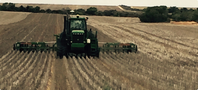
Also due to increasing size in area cropped, limited access to labour and the seeding window for optimal yield is narrowing, there is an unwillingness to reduce seeding width of machinery that are commonly 60ft/18m.
Current options for matching machinery to an 18m seeder:
1) 18m header front
These are emerging into the market and can have some associated challenges with swathing, spreading straw and logistics of harvesting higher yielding crops, including distance travelled before unloading and difficulty unloading into a chaser bin from the main wheeltracks.
2) Two 12.2m seeders
This is a neat 3:1 matching ratio and requires two smaller tractors that can provide versatile use for more operations i.e. spreading, chasing.
However for low rainfall areas sourcing tractor drivers can be a challenge. Widening seeding row spacing to increase speed and increasing bin capacity can help achieve similar coverage to a larger seeding bar, although risks of weed infestation at wider row spacing and potential yield penalties need to be considered on a farm-by-farm basis.
3) Compromised 2:1:3 system
This system uses an 18m seeder, 36.6m sprayer and 12.2m header.
There is some overlap required on the edge of the paddock by either the seeder or the sprayer and header to line up the seeding and spraying wheel tracks.
The header lines up on the main wheel-tracks every fourth run.
The compromised system is becoming the preferred option for many growers.
It can achieve 18% wheel track coverage of a paddock.
This is not the 9-12% target of a 3:1 ratio but better than an unmatched system which results in approximately 40% of the paddock wheeled (often higher if duals are considered).
Setting run lines
It is possible to set up common run lines for all machines using appropriate farm precision agriculture software to take the guess work out of which lines to follow when starting each operation in the paddock.
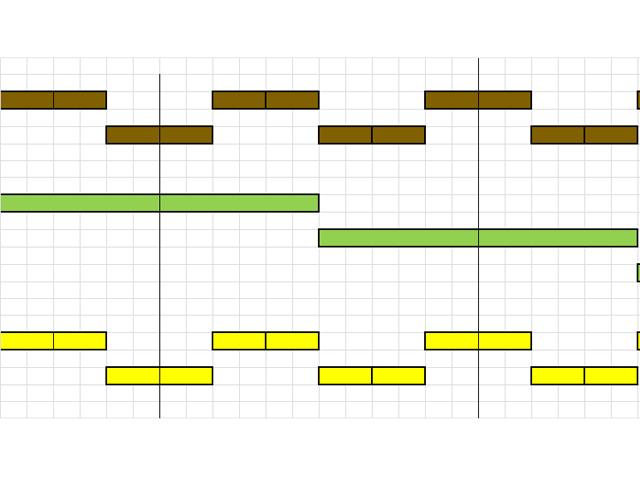
3:1 machinery matching ratio (12:36m or 40:120ft)
For a 3:1 ratio (for example, a 12:36m system) all AB lines can be set from the boundary at the appropriate implement width and the wheel tracks will line up (Figure 1).
2:1:3 machinery matching ratio (18:36.6:12.2m or 60:120:40ft)
Overlapping the sprayer and header in a 18.3:36.6:12.2m requires a bit more planning initially.
The choice of machine to overlap comes down to personal preference.
Some farmers opt to overlap the sprayer and header, because the sprayer commonly has section control so there is less excess input cost.
Others will overlap the seeder as the sprayer is in the paddock 4-5 times.
Growers using this system have observed that it doesn’t really take up extra time overlapping machines as paddocks are generally not perfectly square so some overlap is required on the edges.
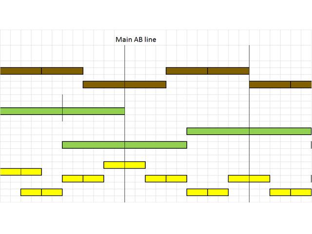
If overlapping the seeder in a 2:1:3 ratio (for example, 18.3m seeder, 36.6m sprayer, 12.2m header) use the first sprayer runline as the main AB line for all machines (Figure 2).
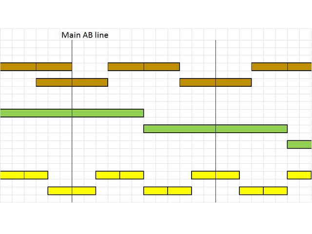
By overlapping the sprayer and header the sprayer will match every second seeder run and the header will have its own wheel tracks in between.
The third seeder runline will be the main AB line that will match the tracks of all machines (Figure 3).
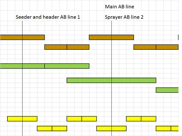
The following method will help set up common run lines in a 60:120:40ft system for overlapping the sprayer and header.
- Create accurate boundaries either by driving the boundary or using a coverage map. Ideally use an RTK 2cm GPS signal however a slightly lower accuracy GPS system such as the RTX Centerpoint (4cm) is proving to be a workable option as long as it is set up correctly. Accurate boundaries are critical as your machine guidance will be working from these surveyed boundaries to steer the outside laps! They are also important for machines fitted with auto-switching and section control seeders switching off on headlands prior to it being seeded.
- Seeder 18m: From the selected edge of the paddock you will need to set a main AB line or master runline (choose a name you will remember). This will be three seeder widths from the boundary. Set the swath width to 36.6m then use it to create the master runline from the boundary.
- For the 36.6m sprayer, the first outside lap is a full sprayer width run which is also set from the boundary. For the second spray lap, create a 9m offset back towards the boundary which should be compensated for on the boom by the auto section control. This step needs to be done in the paddock then once you have driven these run lines you can re-export them back to your software for duplication. Alternatively, you can import the main AB lines from the farm software and do the 9m shift in the display once they have been imported, but do not move them back to the software.
- Header 12.2m: There are several ways to do this. You could set up headland guidance at the same time then use this for the first two laps and overlay it on to the master AB. This will give you a line with only 3m of crop (the required overlap on the header) and also allows for mis-shaped paddocks. Alternatively, start on the master runlines in the paddock and work back from these, which will leave the 3m (or more) depending on the paddock shape to clean up.
1:3:2 machinery matching ratio (24:12:36m or 120:40:80ft)
In a 24.4m seeder, 12.2m header, 36.6m sprayer system the second run of the seeder sets the main AB line for all machinery (Figure 4).
Using different guidance systems
Once common AB lines are created they can be exported along with paddock boundaries and uploaded in to the guidance screens in the cab of all machines.
John Deere and Trimble systems operate different geographic straight line guidance calculation so you must remember this when operating a mixed guidance fleet.
You can record runlines in a John Deere machine to calculate with the Trimble system (non-John Deere guidance 2) but not the other way round. To get around this problem some farmers have driven a machine with each system behind the other to set the master AB line in the paddock.
However if the non-John Deere guidance 2 is not used, AB lines can often be up to 0.5m out in a 1km run therefore using one type of guidance system if possible is preferable.
Acknowledgements
DPIRD and GRDC project DAW243 Minimising the effect of compaction on crop yield.
Co-authors of this article were Nigel Metz, South East Premium Wheat Growers Association and Julien Coles, Precision Technology Solutions.

