This activity is covered by legislation
An owner or occupier of land must give at least 90 days notice to the Commissioner of Soil and Land Conservation of an intent to drain subsurface water to control salinity and discharging that water onto other land, into other water or into a watercourse, even if on the same property. The notice must be in writing using the notice of intent to drain or pump (NOID) form. Principles and guidelines for inland drainage are covered in the Policy framework for inland drainage.
For proposals to drain land within the Peel–Harvey Catchment, proponents must submit a notice of intent to drain or pump water (NOID) to the Commissioner at least 90 days before discharging that water onto other land, into other water or into a watercourse.
Why use siphons?
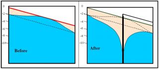
Siphons are a relatively cheap – compared to pumping – and effective way of lowering watertables and preventing salinisation on hillside seeps where there is sufficient land slope and suitable aquifer conditions. Siphons are used to convert widespread discharge (the seep) to a point of discharge. Land managers can minimise economic and environmental damage from discharge by choosing safe disposal points. The effective drawdown of a siphon system depends on transmissivity of the aquifer leading to the bore and a good fall to the siphon discharge point (Figure 1).
Other options to siphons
- Where the seepage is fresh water, many land managers have scooped out the area to act as a small dam for livestock water. Water can also be pumped to a water tank or earth tank for reticulation.
- Small to medium areas of seepage that are not spreading can be fenced and planted with trees and shrubs that are salt or waterlogging tolerant.
Where siphons work best
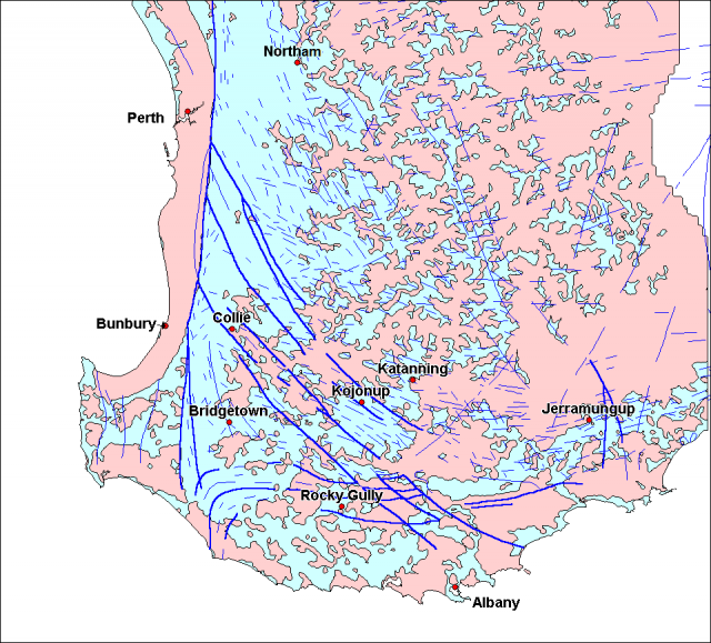
Siphons work best on natural hillside seeps where the landscape has a good fall to a disposal point (Figure 1) and the aquifer has good transmission. Site-specific conditions that determine the successful use of siphons are: relative slope, rate of discharge, permeability of the aquifer material, radial extent of drawdown and availability of adequate disposal options. In general, there is potential to use siphons in most of the dissected country east of the Darling Scarp (Figure 2).
Sites most likely to suit siphons
Sites:
- that are in the middle of a large, natural hillside groundwater seepage
- that have a gradient from the seepage area of at least 1.5–2% to maintain the siphon vacuum
- where the seepage area is more than 5m above a safe disposal point
- where groundwater yield from the siphon is greater than 0.2 litres per second (L/s)
- where the bore is drilled to basement in weathered granite or fracture zones, not dolerite dykes
- where groundwater levels in bores are at or above the ground surface (Figure 3).
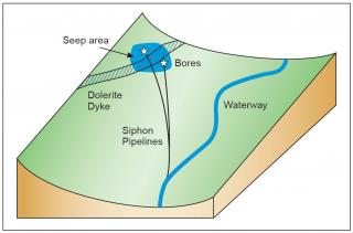
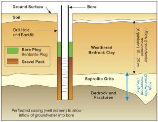
Bores drilled into dark-brown (dolerite) clay often produce low flows. Bores drilled into light-coloured sandy clay, grits and saprock produce higher flowing and more effective siphons. Evidence of large quartz fragments is a good indicator that permeable aquifers could be found at depth. A highly transmissive aquifer – zone of rapid groundwater movement – is a horizon of poorly weathered bedrock called the ‘saprolite grit zone’. The saprolite grits contain fragments of poorly weathered bedrock, are normally about 5 m thick and are found at depths of 15 to 25 m. Although occasional water-bearing fracture zones in the underlying bedrock do exist, it is expensive and risky to drill into the bedrock to find them.
Hillside seeps
Hillside seeps are found in the hilly areas of the western grainbelt of Western Australia – and occasionally further east in lower rainfall areas – where sufficient land slope and aquifer conditions exist. Water quality at these seepages can vary from relatively fresh to saline. Seepages usually become saline and require management and remediation.
Hillside seeps are either geologically or topographically controlled, and occur as a result of groundwater rising to the surface because of a geological impediment to subsurface flow (for instance, behind a dyke), a near-surface bedrock outcrop or hillslope convergence.
Groundwater siphon description
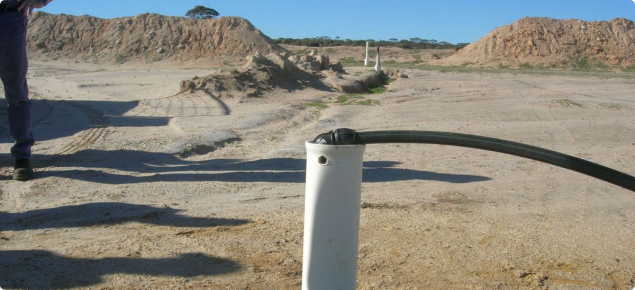
A groundwater siphon is a fully primed pipe inserted into a bore or deep pit that acts like a passive vacuum pump. Provided the outlet of the pipeline is at a lower elevation than the water level in the bore, groundwater will move in the direction of the outlet because it is at a lower (hydraulic) pressure. Gravity pulls the water through the pipeline in the direction of the lowest elevation. In practice, and given the right conditions, siphons can lower watertables to about 8.3m.
Siphons can significantly lower groundwater levels beneath saline seeps if the flow from the siphon (or multiple siphons) is greater than the flow of groundwater to the site.
Construct the siphon using a vertical pipe, which extends down the inside of the bore, and a horizontal pipe (of the same diameter) that extends along the surface. Use a simple elbow-pipe joiner to connect the two pipes. The vertical pipe should reach the bottom of the borehole to reduce the potential for silt accumulation in the bore and to ensure the maximum possible drawdown.
When a groundwater siphon is activated, the water level within the bore falls and friction within the pipeline increases. As a result of this friction, the outlet of the pipe needs to be significantly lower than the original bore water level and below the level to which the watertable is to be lowered.
Bore construction
Bores in south-west Western Australia normally have a drilled diameter of about 100 mm, allowing the insertion of a 50 mm diameter PVC casing pipe. The average depth of siphon bores in south-west WA is about 25 m. Commercially available perforated well (bore) screen and gravel pack should be inserted in the bottom 6m of the bore (Figure 4). We recommend longer well screens and more gravel pack where aquifers are thicker. Develop and clean the bore hole before inserting the siphon pipe into the bore casing.
Selecting the correct siphon pipe diameter
For siphons to work, the pipeline must be sufficiently long to draw maximum flow rates of water from the bore, and sufficiently small in diameter to ensure high water speed. Smaller diameter siphons require lower flow rates. For example, a groundwater siphon with an internal pipe diameter of 25.4 mm will require a flow rate greater than 0.16 L/s, while a groundwater siphon with a pipe diameter of 50.8 mm will require a flow rate greater than 1.26 L/s to prevent gas build up (Table 1).
| Internal diameter (mm) | Critical flow rate (L/s) | Critical flow rate (L/min) |
|---|---|---|
| 19.05 | 0.07 | 4.2 |
| 25.40 | 0.16 | 9.6 |
| 31.75 | 0.30 | 18.0 |
| 38.10 | 0.53 | 31.8 |
| 44.45 | 0.85 | 51.0 |
| 50.80 | 1.26 | 75.6 |
The minimum gradient or slope for a siphon to operate
Smaller diameter pipes require lower downhill gradients than larger diameter pipes. Bores with a water flow greater than 0.2 L/s and with a high operating water level (the stable water height in the bore when the siphon is operating) require lower gradients to be effective. Most groundwater siphons (less than 35 mm in diameter) require a gradient greater than 1.5%. Some sites and conditions may require gradients greater than 2%.
Caution: bubbles and salt with siphons
- During siphoning, gases are released from the water into the pipeline. These bubbles can accumulate and stop the siphon from working. If siphon flow rates are above the critical values, groundwater gases will be expelled from the pipeline. Gas relief valves may be needed at the highest point of the siphon if the flow rate is less than the critical value.
- After saline watertables are lowered by siphons, salt accumulated in the soil needs to be leached out before full productivity can be achieved. Leaching occurs more easily on lighter-textured soils.
Impact on saline areas
An evaluation of siphons in south-west WA found that:
- the radial distance of drawdown by the siphons can range from 50 to 130m and is site-dependent
- watertables can be lowered by at least 2 m within 18 months
- maintaining the flow is important in dewatering a site because of the rapid rise of watertables after siphons cease to flow
- site selection is determined by geological and topographical features
- single siphons are effective in small areas, and multiple-siphon systems should be used for larger areas
- reclamation of the site depends on the ability of accumulated salts to leach down the soil profile
- deep-ripping and other soil amelioration techniques (e.g. gypsum) may be required to enhance the rate of salt leaching and land productivity recovery
- the impact of siphons is limited by a high degree of spatial variability of hydraulic conductivity, and low permeability of many soils.
Cost
Note: the values in this section are indicative only. Cost of materials and services can change rapidly, so we recommend checking prices before committing to works.
A typical siphon bore (100 mm drill diameter, 50 mm PVC casing, drilled to a depth of 25 m) is likely to cost $2500–3000, assuming only one bore hole is needed. A siphon pipeline and related fittings is expected to cost an extra $500–1000. Experience has shown that about 30% of bores do not deliver good flow, and therefore drilling budgets should allow sufficient funds for additional bores. Drilling within an active seepage area and avoiding dolerite soils will give the best likelihood of good flow.
Common law
You can be liable under the common law for damage caused to a neighbour’s property by the construction or operation of drainage. Therefore, assess likely impacts on neighbouring properties or receiving waterways before committing to works. Seek written consent from any person that may be affected by the drainage works, to minimise the risk of legal action for subsequent damages.
References and more information
- Dogramaci, S & Degens, B 2003, Review of engineering and safe disposal options, Water and Rivers Commission, Salinity and land use impacts series, SLUI 20, Perth.
- Salama, R, Ali, R, Pollock, D, Rutherford, J & Baker, V 2003, Review of relief wells and siphons to reduce groundwater pressures and water levels in discharge areas to manage salinity, a report to Water & Rivers Commission, WA, CSIRO, Australia accessed 13 September 2022.
- Seymour, AJ & George, RJ 2004, 'The process and environmental impact of bore siphons in mitigating dryland salinisation', 1st National Salinity Engineering Conference, 9–12 November 2004, Perth, Western Australia.

