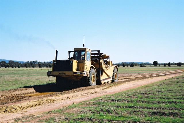
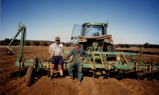
The information in this table is only a guide – seek expert advice before planning, and use expert contractors for construction where necessary. Each landholder has a duty of care to make sure that flows from earthworks are not discharged indiscriminately on a neighbouring property and that stream flows are not significantly diminished or degraded.
See Conservation earthworks legal requirements of landholders for more information.
Advantages of raised beds
Raised beds:
- reduce waterlogging
- provide a deeper seedbed and rooting depth
- provide better drainage from the root zone which may reduce salinity in the root zone
- result in minimal compaction from traffic
- are designed to provide safe and legal disposal of excess water
- improve efficiency of farming operations.
Raised bed systems shed more water because ponding is prevented and surface drainage is more efficient. Drains and discharge points must allow for this.
Drainage design
Drainage has to deal with inflow, raised bed furrow discharge, and discharge from the site. We recommend that raised bed systems are part of an integrated surface water management system. Drains, banks and other earthworks upslope and upstream of the raised bed area need to channel water through or around the raised bed area to prevent flooding.
Raised bed furrows discharge into cross drains or catch drains; cross drains discharge into catch drains; catch drains discharge into constructed waterways; constructed waterways can discharge into a natural drainage course.
The important steps in drain design are:
- carry out a hydrological survey
- calculate the width of the channel to control flow velocities
- design the slope of the sides of the drain to prevent erosion and allow machinery traffic: we recommend a maximum slope of 1 vertical to 6 horizontal units (1:6).
Cross drains will generally have a much smaller catchment and the channel width is less than for the main drain. For machinery traffic, we recommend that the minimum channel width should be the diagonal wheel base of the largest machine that will traverse the drain.
Allow sufficient space for comfortable turning of all the machinery on the bank, not in the drain channel.
Survey the site first
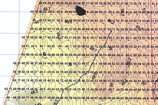
Precision contour surveys are essential on low slope country
Precision contour surveys are needed to:
- detect the dominant direction of slope
- identify humps and hollows that will change the direction of surface flows
- identify the need for local drains or ‘cross drains’ to remove water from small depressions
- plan the orientation of raised beds and the best location to dispose of water from the major drains at the lower end of the raised beds.
Most land prone to waterlogging has a low slope (<0.5%) and shallow duplex soil. Shallow topsoil means that grading or landplaning paddocks – to ensure surface water flows in the dominant direction of the land’s slope – is not usually an option.
You need precision contour survey maps with 10 cm contours. Use differential GPS (DGPS) to get this level of accuracy, and we recommend using an experienced contractor.
Fill or drain minor hollows in the furrows to avoid ponding. Ponded water in the furrows of raised bed systems causes the bed to subside and leaves any crop on them susceptible to waterlogging.
On more sloping country (slopes >0.5%) precision contour surveys may not be needed because the slope direction is much less likely to be altered by minor elevation changes. An example of a precision contour survey is shown in Figure 1.
Layout and design of a raised bed system
We recommend 5 steps to get an effective raised bed system:
- Bed orientation
- Surface drainage
- Access
- Matching machinery to the layout
- Drain orientation and operations
Bed orientation
We recommend orienting raised beds approximately north–south to allow for an even exposure of the bed to sunlight, which maximises the chances of uniform crop development across the full width of the bed. The growing period in Western Australia is during the mild wet winter, when the sun is in the north.
If the major direction of slope is not north–south, there is usually enough sideslope for the beds to be placed on this orientation and still have the furrows run water.
Crops planted on a predominantly east–west orientation have the rows closest to the northern shoulder of the bed exposed to sunlight for most of the day. This causes greater soil evaporation from the northern shoulder and results in one or two crop rows growing less well and yielding less than the crop rows on the rest of the bed.
Where paddocks have a long east–west axis, cropping operations are more efficient with beds running east–west.
Surface drainage
There are 3 types of drains for disposing of water from raised bed systems: cross drains, catch drains and waterways.
Cross drains
Cross drains remove water from small areas within a field where water ponds: ponding is usually a consequence of rises (humps) in the ground surface that are high enough to reverse the direction of slope and surface water flow.
Cross drains usually need to extend only a short distance across-slope to the nearest point lower than the lowest part of the depression they are to drain. Their length must extend far enough across-slope for their channel to have a gradient that will cause water to flow to the nearest area with lower furrows.
Because cross drains conduct water across-slope, they will lie at an angle to the direction of the raised beds. Their beginning and end points are the furrows between the beds. At their exit point, the direction of flow becomes that of the general orientation of beds (Figure 2).
Spoil from the excavation of these drains can either be spread thinly on land either side of them or placed between a cut either side of a median strip. The first alternative is appropriate where the required capacity of the drains is small. The second alternative, which makes the structure a broad channelled W-drain, is appropriate where flows will be considerable. In such circumstances the median strip needs to be broad-based so that machinery can easily cross it.
Where a low ridge extends across the full width of an area to be bedded, cross drains need to extend the full distance and empty either in to a W-drain or onto a well-grassed surface of an adjacent area that is not bedded. In this special case these drains become catch drains.
Catch drains
Catch drains collect the water flowing from the end of all the furrows in a field or section of a field that is separated by other catch drains. Their purpose is to carry all the run-off and drainage water from the furthest point of the catchment of beds across-slope to a safe disposal area. The safe disposal area may be a constructed ‘waterway’ or natural watercourse.
Capacity of catch drains
The capacity of catch drains must be sufficient to carry the peak flow: the peak volume from the upstream catchment, combined with all flow from the raised bed system.
Catch drains must collect and conduct water from the full width of an area of raised beds to ensure the water is removed from the field and placed back into the natural drainage line or creek. They do not need to have a single exit point, but all exits must safely dispose of the run-off within the catchment of origin. Large raised bed systems may have several catch drains with their own safe disposal points.
Catch drains should have a wide channel with the capacity to carry all the flow at a shallow depth, and therefore slow velocity. The channel also needs a firm base to allow farm machinery to cross it on runs up and down the beds.
Catch drain channels:
- need to be excavated with the base level with or below the furrows that drain into them
- must have a cross-slope gradient that will cause water to flow towards the disposal point(s).
Trafficability of catch drains
Farm machinery will need to pass through these drains to turn and run along the next set of beds. The drains must function to prevent water ponding in them, creating conditions where machinery that is crossing leaves deep wheel ruts in the channel or gets bogged.
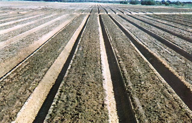
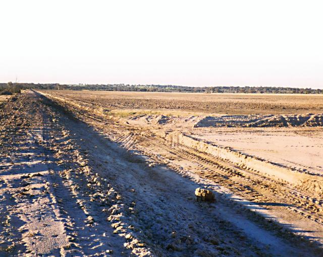
Spoil from large excavated channels should be used to form a broad-based bank on the downstream side of drains. The bank can provide an all-weather access area on which to turn or park farm machinery (Figure 3).
Waterways
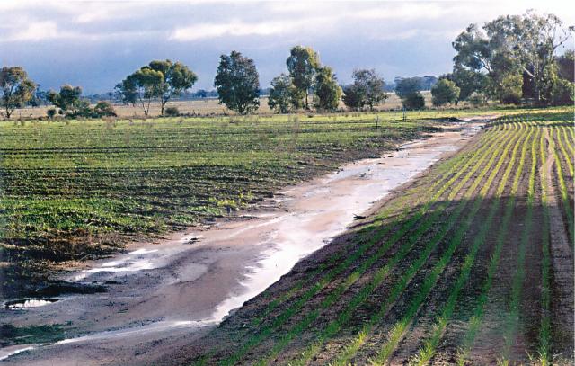
Waterways are broad-channelled, large capacity drains that carry water from upstream past and/or from an area of raised beds back to the natural drainage course. They are excavated to provide a smooth, broad channel (to maintain low depth and therefore reasonably low velocity flows) and to ensure their gradient is consistently in the downslope direction (Figures 4 and 5).
Waterways need all-weather crossings built into them.
Access
Access will be required for:
- delivering seed and fertiliser when sowing
- removing grain during harvest
- directing the movement of stock out of the raised beds when managing pasture
- fighting fires, should the need arise.
Access is more important in large raised bed systems. A useful guide is that for every 600 m length of beds, ‘W’ catch drains should be installed across beds and the broad-based median strip of the drain used for access. Also, if the paddock is wide, a normal (flat) seedbed should be left unbedded at similar intervals (600 m) to be used as a traffic lane up-and-down the slope, parallel to the beds.
Matching machinery to the layout
Match the layout of raised beds to the widths of sprayers, seeders, fertiliser spreaders, swathers and harvesters. Although an exact fit is not essential, it is certainly desirable.
Sidelands with a normal seedbed can be used as an area whose width is flexible and can therefore be widened or narrowed to accommodate the planned numbers of machinery passes in the beds.
Drain orientation and operations
Wide drains at right angles to the direction of beds provide safer and more effective crossings for machinery. The wider the machinery, the more important the angle of the drains.
If the orientation of the drains has to be at a considerable angle with the beds, as a machine exits the beds some parts of it will have gauge wheels 10–15 cm lower than the base of the furrows, while the remainder will have its gauge wheels at the correct height for the beds.
Also, an angled entry and exit creates a ‘pitch and roll’ effect, which wears the machinery and causes some discomfort for the operator. If a drain has to be at an angle to the direction of the beds, the drain must have a channel width of at least as wide as the diagonal wheel base of the power units (tractors, self-propelled sprayers, seeders and harvesters).
Wide drain channels minimise pitch and roll stresses and strains on machines and operators, and improve accuracy of depth or height control.
Capacity of catch drains
The capacity of catch drains is determined by the total number of, and the rate of discharge from, the furrows that discharge into them. This volume of flow can be considerable. However, because the capacity of catch drains must be large enough to safely handle all the run-off and drainage from raised beds, a limit has to be imposed on the size of the area of beds draining into them. Layout designs that limit the area of beds will ensure the required dimensions of catch drains are constrained and thus practical and not too costly.
The amount and rate at which run-off water discharges from a furrow is controlled by particular combinations of:
- land slope
- depth of water in the furrow
- rainfall intensity
- length of furrow.
When these factors are combined with the maximum permissible velocity of flow (that is, a velocity below which erosion will not occur) they produce a maximum length of furrow for a range of slopes. The theoretical maximum length of furrow on a 3% slope is about 600 m. Longer furrows build up depths of water to levels where flow velocities become erosive. On lower slopes this theoretical maximum length increases, and practical considerations relating to the capacity of catch drains and the disposal of their drainage water become more important, as do the considerations discussed in the section on Access. These also act to limit furrow length.
Once the maximum length of furrow is decided, the required capacity of the main catch drains can be determined. The volume of flow entering main catch drains can be considerable (Figures 6 and 7).
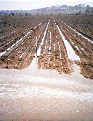
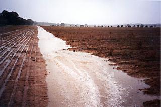
As in furrows, the velocity of flow in catch drains needs to be limited to a maximum permissible velocity that will not cause erosion. The control of flow velocity in catch drains (Figure 6) is achieved by:
- limiting the total discharge of water entering from furrows (by controlling the length of furrows and the number of furrows entering the drain)
- controlling the depth of flow in the catch drain at full capacity (by widening the channel).
A wider channel will ensure catch drain discharge flows at a shallow depth and, therefore, a slow velocity. However, the velocity of flow is also strongly influenced by the slope of the floor of the catch drains.
Because raised beds will be mostly aligned up-and-down the slope, catch drains will most often be required to move water across the slope. The natural gradient in their channel is thus always likely to be small, and small gradients produce slow flow velocities. However, slow flow velocities mean the channels of catch drains have to be wide for them to have the capacity to carry the required volume of water.
Excavate the channel slope to ensure that water flows at a velocity which will not cause erosion and is sufficient to empty the drain as quickly as possible. Drains that empty promptly and completely prevent the channel from becoming too wet and difficult to drive through. Catch drains with sections of their channels that pond water will be soft and result in deep wheel ruts which will reduce the efficiency of the drain.
Slope limits for furrows and drains
There are 2 important factors that affect the velocity (and erosivity) of run-off flows that need to be considered:
- the slope of the furrows
- the slope of the furrow entering cross or catch drains.
The theory used for predicting the velocity of flow in furrows suggests raised beds with the furrow dimensions that match a 45 cm tractor tyre can be safely installed on slopes up to 3%, provided the length of furrow does not exceed 600 m.
Furrow flow velocities on slopes greater than 3% are likely to cause erosion problems in the furrows and the catch drains, and are not recommended for raised beds. Where channels of cross or catch drains have to be excavated to obtain the desired flow direction and velocity, the slope of furrows as they enter the drains will increase substantially. An increase in flow velocity at this point can cause erosion, which may alter the height of the bed above the furrow base and cause difficulties with seeding and harvesting.
Make the slopes at the point of furrow entry into cross or catch drains as low as possible, and not exceed a gradient of 1:6 vertical to horizontal distance. Slopes lower than 1:6 will reduce the risk of erosion and be safer for machinery entry and exit.
Constructing raised beds
Before you form the beds
Soil to be used for raised beds must have:
- a stable soil structure
- a porous and permeable soil
- a deeper-than-normal seedbed.
These soil conditions will:
- drain and aerate freely, reducing the risk of waterlogging
- increase root growth and proliferation, which reinforces soil structure, minimises subsidence and increases soil organic matter
- increase plant water use, which increases production, and reduces deep drainage and watertable recharge.
Creating desired soil conditions
Deep cultivation
Deep cultivation is recommended prior to forming the beds because it:
- removes the compact traffic pan that exists in all agricultural soils between 8 and 18 cm
- facilitates the excavation of furrows to 20 cm below the normal ground surface
- incorporates the top of the B-horizon soil in the tilth and make the transition to the B-horizon less abrupt
- improves the water-holding capacity of the beds in shallow sand over clay soils through the inclusion of some of the clayey B-horizon in the tilth
- increases the infiltration capacity and makes waterlogging less likely
- increases the amount of water that is easily available to plants.
This deep cultivation should, if possible, be done when the soil moisture content is at the lower plastic limit, (the moisture content at which the soil just becomes plastic and is able to be moulded). At this moisture content, cultivation creates the largest amount of aggregates with the most uniform size distribution. Damage to soil structure by way of pulverisation (when the soil is too dry) or compaction (when the soil is too wet) are avoided. This requirement does not apply to sands.
Forming beds
The single most influential change in management to achieve this objective is a commitment to adapting the track width and tyre size of machinery, which will prevent traffic compaction on the soil in the beds. A 100% controlled-traffic regime is a prerequisite to maximising the performance of, and return from, raised beds.
The choice of track widths of 1.83 m and multiples of this width and 0.45 m tyre width require no factory approval to retain the manufacturer’s warranty and are the best against all of the criteria.
Newer machinery may have 3 m centres for wheel tracks and 0.6 m wheel widths. For this spacing, mounds will be 2.4 m wide and furrows will be 0.6 m wide, which will result in:
- less root-zone drainage
- less soil excavated from furrows resulting in lower bed height
- increased water flow along furrows because fewer furrows have to carry more water.
As beds get wider and shallower, the benefits reduce. Therefore beds not used for machinery traffic are still recommended to be 1.83 m wide
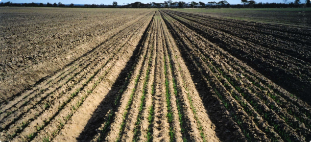
The objective of raised-bed farming is to create and maintain soil conditions that will allow soils to drain and aerate and so prevent waterlogging (Figure 8). The operation of farm machinery must be consistent with this objective if the investment of time, effort and money put into raised beds is to gain maximum return.

There is no single, best track width and tyre size (bed spacing and furrow widths) provided soil conditions in the beds are created to ensure they will drain and aerate. The choice of a standard track width and tyre size for machinery used should be based on practicalities and cost, and depends on the:
- difficulty and cost of adaptations
- versatility of adapted machinery
- return on the investment of time and effort
- resale value of adapted machinery.
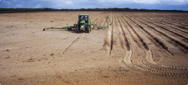
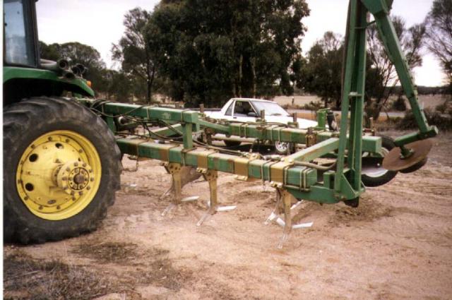
Bed-formers (Figure 9) can be supplied as three-point linkage or trailing models. New machines will cost between $30,000 and $40,000, depending on the variety of detachable components purchased to add to its versatility.
Some growers have made their own bed-formers by converting old rippers or deep cultivators. These often have hydraulic stump-jump rams on their ripper shanks. Mostly they are trailing machines and the cost of a second-hand ripper and its conversion to a bed former is about $12,000 to $15,000.
The old rippers that have been converted to bed-formers lack the versatility of the specially made machines. In particular, their framework limits options for rearranging components to allow the machine to renovate existing beds.
Preventing erosion of drain channels
Preventing erosion of the channel of catch drains and waterways is a major challenge for sustainable raised bed farming. This is particularly so on sandy soils that are highly erodible. The quantity and velocity of flow in catch drains and waterways can be considerable and hence the potential for erosion can be high.
The most important requirement for preventing erosion of the channels of drains is to have a good cover of vegetation at the time when flows are going to be largest and most frequent. In a winter-dominant rainfall regime, this time is in June and July.
Meeting this challenge in cropping systems that rely on herbicides for weed control makes the task even greater. There are 2 possible solutions:
- vegetate the channels of catch drains and waterways with a mixture of a prostrate perennial grass and an annual legume
- vegetate the channels with a particularly hard-seeded variety of subterranean clover.
The former option will involve grasses like kikuyu or couch and clovers like balansa or a suitable variety of subterranean clover. Maintaining a sward of this type presents major operational challenges if herbicides are not to kill it. Crop rotations and the passage of sprayers using grass and broadleaf herbicides will mean the sward will be subject to spray applications that will kill both types of plant.
Such potentially lethal applications of herbicide will occur no matter how careful and conscientious an operator is in turning off and on the sprayer as it enters and leaves a drain channel. Hence, if this option is chosen there will be an ongoing management requirement to maintain such a sward.
Another significant drawback with this option is the risk of grasses, like couch and kikuyu, invading the cropping area of the beds.
The second alternative of using a hard-seeded sub clover is likely to be much less of an operational challenge and far less of a potential weed problem in crops. Hard-seeded annuals like sub clover can survive some herbicide damage because of the reserve of hard seed they create in the ground. Furthermore, because they will remain ungrazed throughout the growing season, they will be always be able to flower and set seed, and thus increase the reserve of hard seed over time.
Subclover has an additional trait that increases its potential as a good erosion preventative cover for drains in paddocks of raised beds. Its habit of burying seed increases its potential to persist for long periods, and the growth habit of anchoring a mat of vine to soil over summer will provide good protection against erosion.
Establishing vegetation in drain channels
Despite the best time for the construction of drains and beds being the spring before the first crop, most farmers will want to do this work in the summer–autumn period between crops. Such a works program will mean drains will be sown in the same season as the first crop on beds.
If this situation applies, the better operational alternative is to seed the drains after some rain as early as sensibly possible to enhance pasture establishment before the crop seeding program.
Further, because of the need to have a reserve of hard seed in the ground to achieve sward survival through the weed spraying program, the seeding rate is recommended to be up to twice the rate recommended for normal pasture establishment.
Renovating raised bed systems
Why renovate?
Raised beds will gradually slump and compact (consolidate) because of:
- wet conditions, and wetting and drying of soil in the beds
- imperfect machinery tracking
- livestock movement (where present)
- seeding machinery disturbance.
The rate of consolidation of the beds depends on soil texture, drainage of the soil and wetness of the season. In some soils and seasons, 60–80% consolidation can occur in one growing season. Where farms with raised beds have sheep and the raised beds are grazed over summer, bed renovation every second year is likely to be beneficial. It may even be beneficial every year, prior to seeding.
Renovation is necessary whenever:
- the beds have been damaged by traffic or grazing and have lost their flat-top, square-shoulder appearance
- when they have subsided and become compact
- when the furrows have lost their depth or have accumulated soil and trash that impedes water flow.
Renovation should aim for:
- zero soil inversion – no mixing of topsoil and subsoil
- retention of roots, stems and leaves with as little disturbance as possible
- clean and compact furrows to ensure they empty all water and retain trafficability for in-crop operations during the next winter
- low cost operation.
Renovation machinery
Machinery should renovate beds with:
- minimal damage to soil structure
- minimal disturbance and destruction of root material
- minimal reduction of soil organic matter.
The renovation tools consist of wide, sharply raked, flat blades that are mounted at the base of narrow ripper shanks. Two pairs of the blades are mounted on 2 ripper shanks per bed. These gently cut, lift and break open the soil in beds from their base, level with the floor of the furrow (Figure 10).
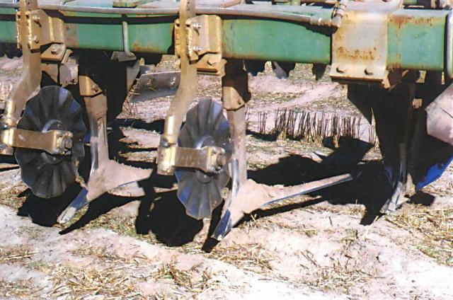
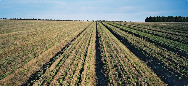
The passage of these renovation tools leaves plants in the beds with enough soil-root contact to prevent the plants from being pulled out by hand (Figures 11 and 12). Also, suspended from the rear of the bed-former bar in its re-configured, renovation-mode are gangs of disc harrows. These gently break any crust on the soil surface and maximise infiltration properties.
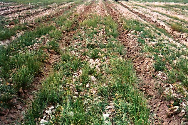
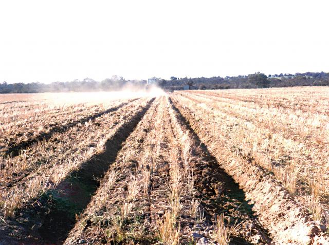
The breaking of any surface crust and the retention of plant tops and roots ensures water will move relatively rapidly in beds at moisture contents considerably less than saturation. Unsaturated soil conditions limit or even prevent dispersion of sodic soil, which only occurs at saturated moisture contents.
Renovation objective
The objective for bed renovation is to break any surface crust while retaining plant tops and roots. To achieve this, use equipment that is developed specifically to minimise capillary rise of salt into raised beds on saltland. This equipment consists of steeply raked, flat and wide-spanned mulch sweeps mounted at the base of rippers (Figure 13).
The mulch sweeps cut through the loosened seedbed at its base forcing the soil to pass over the mulch sweep in the same way as air passes over the top of an aeroplane wing. This lifts the soil vertically about 1–2 cm causing it to break open before it falls back in place. No soil inversion occurs, and any roots are cut and remain in place.
The wavy coulters mounted in front of the ripper shanks cut any straw or vine, preventing build-up of vegetation on the shanks. These coulters also reduce soil heave upwards from the point of the rippers and reduce the draught on the shanks.
Suspended disc harrows mounted on the rear of the bar have adjustable height and rake. They are set to lightly break any surface crust on the soil and clear to one side any prostrate stubble prior to seeding the next crop (Figure 14).
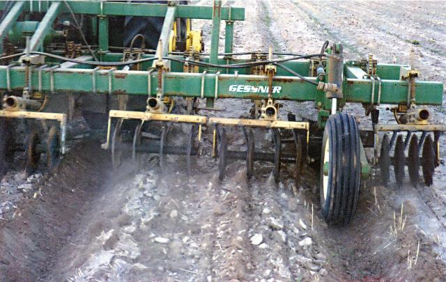
Renovation also cleans and reshapes the furrows, ensuring the flow of drainage and run-off water remains reliable and efficient.
Set-up and operation for bed renovation
The preferred method of renovating beds is to loosen the full width of soil in the bed as deeply as possible, that is, to a depth level with the base of the furrowers, which remain on the bar for the renovation.
To set up the bed-former bar for renovation, the grader blades are removed and 2 narrow ripper shanks per bed are mounted on the front bar, 36 cm either side of the centre line in each bed. These rippers are set to the same working depth as the furrowers.
Left- and right-handed sharply raked mulch sweeps are mounted at the base of each ripper. These have a rake angle of 35-degrees and no tilt from mount-to-tip or from front to back edges (Figure 10). The mulch sweeps act as very gentle blade ploughs, cutting roots and lifting the soil by only about 2 cm as it passes over the blades.
Two additional components are, therefore, preferably attached to the bed-former bar in renovation mode:
- wavy coulters in front of the ripper shanks
- gangs of suspended disc harrows on the rear of the bar.
The wavy coulters are mounted in front of the ripper shanks. Eight sets of disc harrows (2 sets per bed) are suspended on the rear of the tool bar.
The suspended gangs of disc harrows should be set to:
- have very little or no angle
- have only a shallow penetration of about 2cm
- track in the inter-row space of the previous crop.

